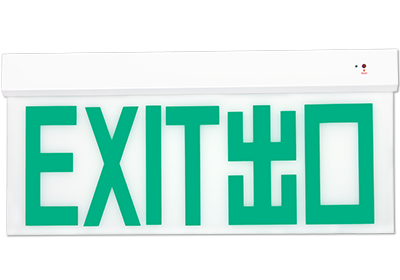
LED EXIT SIGN
HXL WALL MOUNTING
Features
- Intelligent LED exit signs with automatic self-test
- Nichia LEDs with 50K hours life at L70, with IES LM-80-08 certified
- System power is only 2W
- Full solid-state design without mechanical part
- Constant brightness control for both AC and DC operations
- Programmable lamp flashing in emergency mode
- Less than 5°C temperature rise for the whole system
- Deep-discharge shutdown for battery protection
- Optically isolated low voltage test switch
- High efficient switching mode charger with full protections
- Pulse charge mode for full battery
- Less than 12 hours battery recharge time
- High quality light guide panels
- Optional infrared remote control for self-test, system set up and dimming
Electrical Characteristics
| Rated supply voltage | 220-240 VAC (-20%, +10%) |
| Supply frequency | 50-60 Hz |
| Circuit power | 2.0W max |
| Changeover time | <0.1 Sec |
| Recharge time | <12 hrs |
| Rated discharge time | 4 hrs (typical 4.5 hrs) |
| Power factor | >0.8 |
| Lumen Maintenance (L70) | >50K Hrs |
| Discharge cut-off voltage | <1.0V/cell |
| Ambient temperature (ta) | 0 … +50°C |
| Max. temperature rise (Δt) | <5°C |
| Battery type | NiCd |
| Lumen factor | Normal mode: 100% Emergency mode: 120% |
Years Warranty
Hours of LED Life
Watt
LED Chips
They are IES lM-80-2008 (Measuring Lumen Maintenance of LED Light Sources) certified for the best reliability and performance.
For eye safety, the LEDs are also IEC 62471:2008 (Photobiological Safety of Lamps and Lamp Systems) certificated.

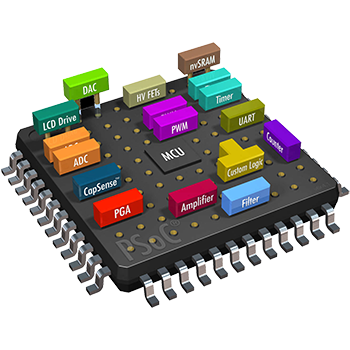
Micro-Controller Controlled Operations
The improves system reliability and makes the system smarter for the whole operations.
Self-test
Charger
LED lamp
System changeover
Battery voltage
Battery discharge
Once fault is found, the red LED indicator will flash with different patterns for various error types.

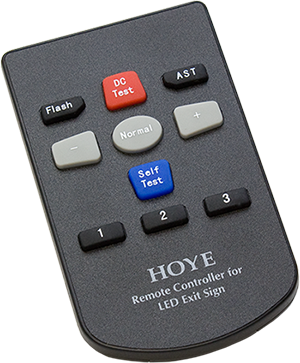
IR Remote Control
The infrared remote control makes maintenance easier than ever. It can be used to set the LED exit sign system settings and self-test functions.
Panel brightness dimming control in normal operation
Flashing model in emergency mode
System changeover test (simulate traditional test button)
On-demand self-test
LED Indications
A rich set of LED indications provide feedback on the system’s status and faults. Operators can use this information to quickly identify and diagnose problems.
| Battery Charging | |
| Battery Full | |
| Battery Discharging | |
| System Errors |
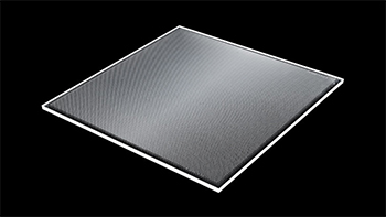
Light Guide Panel
Light guide panel is characterised by high uniformity of light and efficiency.
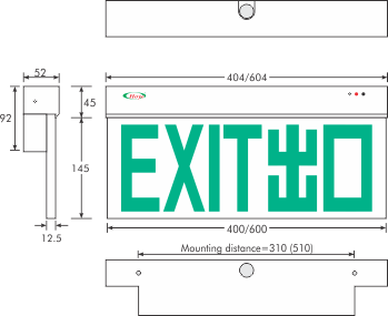
Dimensions
Compliances
FSD Circular Letter No. 5/2021 Requirements for Self-contained Luminaires Emergency Lighting Systems [PPA/104(A) (5th Revision)
BS 5266-1:2016 Emergency lighting – Code of practice for the emergency lighting of premises
BS EN 1838:2013 Lighting applications. Emergency lighting
EN 61347-2-13 Lamp controlgear. Particular requirements for d.c. or a.c. supplied electronic controlgear for LED modules
EN 62384 DC or AC supplied electronic control gear for LED modules. Performance requirements
EN 60598-1 Luminaires. General requirements and tests
EN 60598-2-22 Luminaires. Particular requirements. Luminaires for emergency lighting
EN 55015 Limits and methods of measurement of radio disturbance characteristics of electrical lighting and similar equipment
EN 61000-3-2 Electromagnetic compatibility (EMC). Limits. Limits for harmonic current emissions (equipment input current ≤ 16 A per phase)
EN 61000-3-3 Electromagnetic compatibility (EMC). Limits. Limitation of voltage changes, voltage fluctuations and flicker in public low-voltage supply systems, for equipment with rated current ≤ 16 A per phase and not subject to conditional connection
EN 61547 Equipment for general lighting purposes. EMC immunity requirements
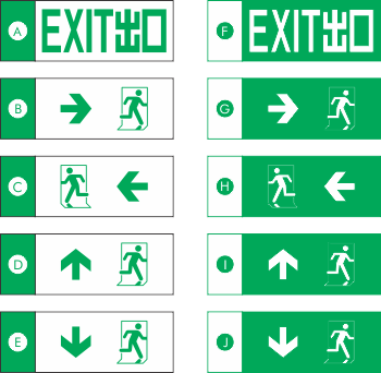
Emergency Exit Legends
Product Models
| Model | Panel Width (mm) |
Illuminated Side |
|---|---|---|
| HXL-W4S# | 400 | Single |
| HXL-W4D# | 400 | Double |
| HXL-W6S# | 600 | Single |
| HXL-W6D# | 600 | Double |
※ Replace “#” for emergency exit legend codes above.