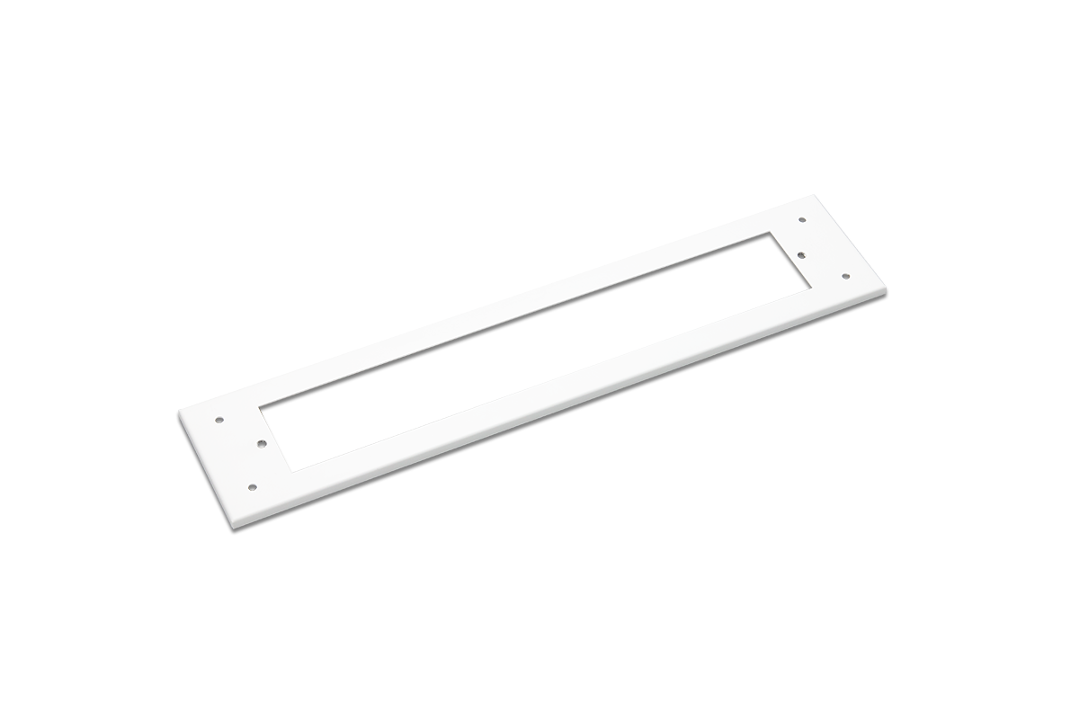
HXS Recessed Series – Directional Pictogram LED Exit Sign
IEC-62034 Automatic Test
![]()

Features
- IEC 62034:2016 automatic test system for HK FSD requirements
- Slim design with 4 mm bezel and 20 mm thickness
- Nichia LEDs with 15 years life at L70
- System power only 2 W
- Full solid-state design — no mechanical relays
- Constant brightness control for AC and DC operation
- Chemistry-aware charging for LiFePO4, NiCd and NiMH
- Precharge recovery for deeply discharged batteries
- Thermal charge protection with automatic resume
- Deep-discharge shutdown for battery protection
- Isolated low-voltage test switch
- Infrared remote for brightness control, changeover test, and Autotest
- Dual LED system status indication (optional LCD status module)
Electrical Characteristics
| Rated supply voltage | 220-240 VAC (-20%, +10%) |
| Supply frequency | 50-60 Hz |
| Circuit power | 2.0W max |
| Changeover time | <0.1 sec |
| Recharge time | <6 hrs |
| Rated discharge time | 3 hrs |
| Lumen Maintenance (L70) | 15 years |
| Ambient temperature (ta) | 0 ... +50°C |
| Max. temperature rise (Δt) | <5°C |
| Battery type | LiFePO4, NiCd/NiMH as option |
| Luminance | 250 cd/㎡ max |
IEC 62034 Automatic Test
According to HK FSD, Technical Guidance May 2021 and FSD Circular Letter No. 5/2021, PPA/104(A), 5th Revision, emergency lighting with self-contained batteries shall be inspected periodically. For automatic testing devices, it shall be designed in accordance with IEC 62034:2016 - Automatic test systems for battery powered emergency escape lighting.
Our test system will start automatically after mains supply is not interrupted for 5 days. After a random delay days for different device, a commissioning test is started. This avoids adjacent devices testings at the same time. Monthly functional tests and annually duration test will then be repeated.
The firmware supports full IEC 62034 - ATS Type S, including the following tasks:
![]()
| IEC 62034/BS EN 50172/FSD Requirements | Automatic Test |
| Commissioning Testing | ✅ |
| Maintenance | |
|
a. Once every month a functional test in accordance with BS EN 50172 not longer than 10% of rated duration should be carried out. |
✅ 60 sec |
|
b. Once every twelve months a full rated duration test, should be carried out and the results should be entered in a register. |
✅ |
|
c. The luminaire should be functioning properly to maintain the stipulated lighting level and the normal power supply should be restored after the test. |
✅ |
|
d. If automatic testing devices are used, the above item a – c should be complied with. |
✅ |
Functional and Duration Tests
Functional and duration tests are two types of tests performed to ensure exit sign functionality and reliability.
- Functional test is performed once a month to check the basic functionality. The test also checks the hardware parameters, such as various voltage and current. The test duration is 60 seconds.
- Duration tests are performed once a year. The tests are the same as functional test but with additional battery life check with a full rated battery discharge.
- Commissioning test is the first duration test. They are typically performed after the device has been installed and configured.
| Test Performed | Functional Test |
Duration Test |
|
1. System Changeover |
✅ | ✅ |
|
2. Lamp voltage |
✅ | ✅ |
|
3. Lamp current |
✅ | ✅ |
|
4. Battery charging voltage |
✅ | ✅ |
|
5. Battery charging current |
✅ | ✅ |
|
6. Battery discharging voltage |
✅ | ✅ |
|
7. Battery discharge time |
✅ |
Automatic Test Flowchart

Years Warranty
Hours of LED Life
Watt
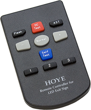
IR Remote Control
The infrared remote makes maintenance easier. Adjust panel brightness, run a changeover test, and clear Autotest faults without opening the fitting.
- Panel brightness dimming in normal operation
- Restore default brightness
- System changeover test (simulates the traditional test button)
- Clear stored Autotest faults after the fault has been corrected
Status Indications
Two LED indicators provide a rich set of status indications for system status and faults. Operators can use the information to quickly identify and diagnose problems.
Normal Status
-
Charging
-
Battery charged
-
Functional test postponed
-
Duration test postponed
Fault Status
- Lamp fault
- Charger fault
- Battery fault
- Battery duration EOL
Compliances
FSD Circular Letter No. 5/2021 Fire Safety Requirements for Emergency Lighting Systems in Licensed/Registered Premises
IEC 62034:2016 Automatic test systems for battery powered emergency escape lighting
BS 5266-1:2016 Emergency lighting – Code of practice for the emergency lighting of premises
BS EN 1838:2013 Lighting applications. Emergency lighting
EN 61347-2-13 Lamp controlgear. Particular requirements for d.c. or a.c. supplied electronic controlgear for LED modules
EN 62384 DC or AC supplied electronic control gear for LED modules. Performance requirements
EN 60598-1 Luminaires. General requirements and tests
EN 60598-2-22 Luminaires. Particular requirements. Luminaires for emergency lighting
EN 55015 Limits and methods of measurement of radio disturbance characteristics of electrical lighting and similar equipment
EN 61000-3-2 Electromagnetic compatibility (EMC). Limits. Limits for harmonic current emissions (equipment input current ≤ 16 A per phase)
EN 61000-3-3 Electromagnetic compatibility (EMC). Limits. Limitation of voltage changes, voltage fluctuations and flicker in public low-voltage supply systems, for equipment with rated current ≤ 16 A per phase and not subject to conditional connection
EN 61547 Equipment for general lighting purposes. EMC immunity requirements
Dimensions


Emergency Exit Legends
Ordering Information
| Model | Width (mm) | Legend | Illuminated Side |
|---|---|---|---|
| HXS-R3SD | 278 | D | Single |
| HXS-R3SE | 278 | E | Single |
| HXS-R3SF | 278 | F | Single |
| HXS-R3SG | 278 | G | Single |
| HXS-R3SH | 278 | H | Single |
| HXS-R3SI | 278 | I | Single |